Certain parameters hold true when designing all gears, including plastic:
Capacity analyses for steel gearing have been practiced for over 100 years and most engineers are aware of the techniques for working with of steel (as well as the properties); both are well documented. Designing plastic gears, on the other hand, presents a whole new set of challenges. This article will look at one of the biggest: temperature.
Designers of plastic gears need to be cognizant of the significant effect of temperature on the gear’s mechanical properties and dimensions. Simply designing the gear set using mechanical properties from material data sheets, without regard for performance under elevated temperatures, may result in gears where teeth deflect more than expected, surface wear becomes unacceptable and mesh contact becomes tight or erratic.
A more accurate method is adjusting mechanical properties and dimensions for temperature changes. This allows gear designers to obtain a much better assessment of gear capacity when designing plastic gears. For example, taking into account the modulus, flank strength, and bending strength of the material as it heats to different temperatures allows gear designers to design their gear to those parameters, drastically increasing the likelihood of designing an effective gear.
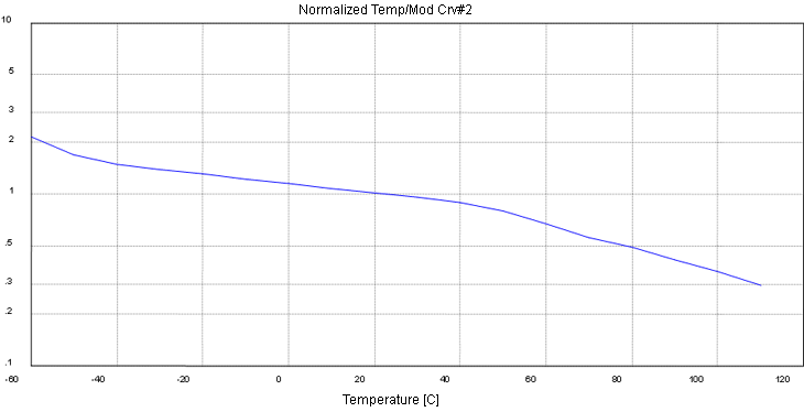
Let’s look at this in practice: Imagine you’ve chosen Acetal as your material. Calculate the gear temperature in mesh, in this case, 68°C. Individual graphs reference modulus, flank strength and bending strength with respect to temperature, allowing material properties to be adjusted to the values exhibited at the computed component temperatures. In this instance, we see that the modulus drastically decreases, resulting in greater deflection under load.

Plot 1 – Modulus
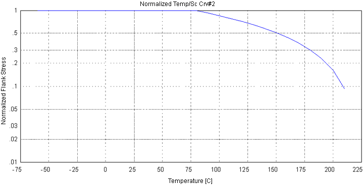
The analysis further reveals a decrease in allowable flank strength as the temperature increases

Plot 2- Flank Strength
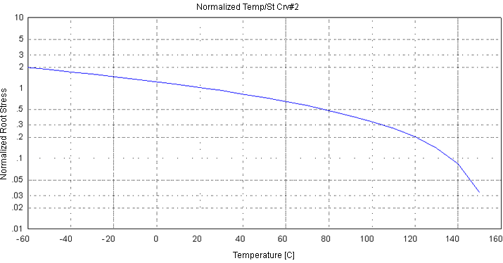
Finally, we see that as the temperature increases, the allowable bending strength decreases as well.

Plot 3- Bending Strength
Computing capacities at these adjusted properties will give the designer a clearer picture of the life expectancy of the gear set under the load and environmental conditions within which the gear set is expected to operate.
The other exercise that is required is to evaluate the mesh geometry of the set under the required environmental extremes. The geometry must be evaluated at the maximum material condition and minimum effective operating center distance as well as at the least material condition and maximum effective operating center distance as computed, taking temperature and humidity changes into account. The first condition evaluates minimum backlash and root clearances, and the second condition evaluates minimum contact ratio. Completing this analysis will give the designer the assurance that his or her design will function acceptably under all required extremes of its operating environment.
Integrated Gear Software (IGS) was used to conduct the analysis in this article. IGS, from Universal Technical Systems, Inc., is an expert system in gear design and manufacture, helping designers eliminate noise and premature failure, reducing trial and error, lowering design and production costs, and speeding time to market.